How to Build Scalable and Robust Live Smooth Streaming Server Solutions
As you may know, IIS Media Services 3.0 includes the latest smooth streaming technology offering – Live Smooth Streaming with which you can do HD quality live streaming with smooth playback experience. Together with Smooth Streaming enabled Silverlight client (link), you also get advanced features like full live DVR, FF/RW, Slow Motion, live Ads insertion, etc. Live Smooth Streaming has been successfully deployed in many high profile online events including the most recent NBC Sunday Night Football. To enable Live Smooth Streaming for such big-scale online events, we not only need to build great streaming and playback features but also need to make sure scalable and robust server solutions can be built to handle the massive streaming load as well as any unexpected failures in the network. So in this blog, I will go through the related server features and discuss how such server solutions can be built by using those features.
In general, live streaming servers take in encoded live streams from the encoders and then make them available to the clients. In order to build server networks for scale and redundancy, they can also take input from and output to other servers. So as the first step, let’s take a look at what are the different inputs and outputs that a Live Smooth Streaming server supports in order to build a streaming topology. One design principle we had was that instead of building the server into pre-defined fixed roles, we enable each server to input and output different types of streams so that they can be used as building blocks to enable various topologies. We think that this approach provides more flexibility and can also help avoid confusions with the definitions of the server-role terms.
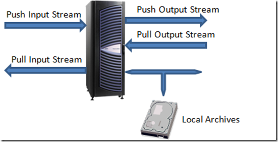
Figure 1 - Inputs and Outputs from Live Smooth Streaming Publishing Point
Figure 1 shows all the possible inputs and outputs that you can configure on a Live Smooth Streaming Publishing Point. To simplify the matter, I’m assuming that each server just has one publishing point and will be using these two terms interchangeably.
Let’s go through them in more detail:
Push Input Stream
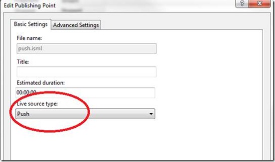
This input is for accepting long running live streams from a push source which uses HTTP POST requests to push data into the server. A push source can be a group of live encoders or another Live Smooth Streaming publishing point (see “Push Output Stream” section). The more common usage of push input stream is to ingest live stream from Live Smooth Streaming encoders which typically supports push outputs. Comparing to using pull, one major advantage of using push stream between encoders and servers is that encoder can stay behind firewalls and does not need to have public facing IP address. Figure 2 as shows how you set up a publishing point with push input stream.
Figure 2 – Set up Push Input Stream
The URL syntax of the incoming push stream is something like: http://server/pubpoint.isml/streams(streamID)
The “streamID” value uniquely identifies an incoming fragmented MP4 stream which is transmitted over a HTTP POST request. One fragmented MP4 stream could contain multiple tracks (e.g. video and audio). In Live Smooth Streaming, typically there are multiple fragmented MP4 streams coming from the encoder(s) to the server. For example, you could have one for each bitrate and use bitrate or resolution values to uniquely identify them.
In terms of enabling redundancy and failover functionalities, one thing important to note is that you can have multiple POST requests (TCP connections) for each “streamID” either sequentially or in parallel. Here is more detail:
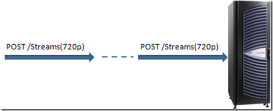
1. In a typical setup, encoder will just use one POST request for each “streamID” to save some bandwidth between the encoder and the server. Each POST request is a long running TCP connection that keeps transmitting data from the encoder to the server. If the TCP connection gets broken or the encoder failed unexpectedly, server will keep the publishing point in “started” state and wait for the new POST request to come in for the same “streamID”. Once the new connection is established for the same “streamID”, server can filter out duplicated fragments if there’s any and resume the live stream. Note that during the time when the connection is broken and server has no data for the live stream, client can still request all the DVR contents that have been already archived. It’s just that those “live” clients would have to wait and retry after encoder resumes the stream. This is one example of multiple POST requests happened sequentially for one “streamID”.
2. Another usage of multiple sequential POST requests is that the encoder could proactively close the current POST request (with graceful chunked encoding transfer ending and TCP shutdown) and creates a new one. This allows the encoder to preemptively take actions and have more control in failover. For example, if the encoder detects any throughput degradation, or the encoder itself is having issues, it could immediately start its failover logic (e.g. bringing up the backup encoder) to minimize the service interruption.
Figure 3 – Sequential Multiple POSTs for Push Input Stream
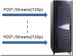
3. If the bandwidth between the encoder and the server is not a concern, you could even have multiple simultaneous POST requests to the same publishing point for the same “streamID”. For example, you can have both primary and backup encoders running at the same time and both of them pushing a stream, say Streams(720p), to the same publishing point. Server has the logic to filter out duplicated fragments that are coming in for the same “streamID”. This is essentially a hot spare setup. If one encoder failed, the other encoder and the server can keep running without any glitch. Once you have another backup encoder set up and ready, you can let it post to the server again at any time to resume the redundancy.
Figure 4 – Multiple Simultaneous POSTs for Push Input Stream
So for Input Push Stream, by breaking the dependency between the stream (as identified by “streamID”) and the POST connection, the server is really flexible in terms of how fragment MP4 streams are coming in. This also enables the encoder partners to build advanced failover logics in the encoder products/platforms. One question you may ask is that since the server always expects new connections for the incoming streams, how does it know when the live stream is actually finished? Good question. In our protocol, we defined a special EOS (End-of-Stream) signal that encoders will send if it was a graceful stop or shutdown. Once the server receives EOS for all streams, it will automatically put the publishing point into “Stopped” state which transitions the live presentation into a pure DVR session.
Pull Input Stream
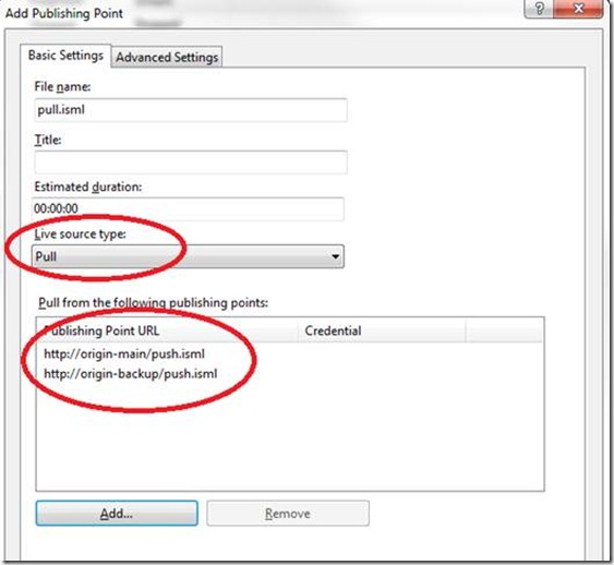
Pull Input Stream is normally used in server to server distribution to scale out the streams. It could also be used to ingest live streams from the encoder if the encoder supports pulling. Figure 5 shows how you can set up a publishing point with pull input stream.
Figure 5 – Set up Pull Input Stream
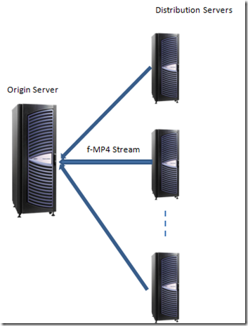
When configured with pull input stream, the server will issue HTTP GET requests to upstream servers to pull down the long running fragmented MP4 streams. The first step is to resolve the publishing point URL to the actual stream URLs (by appending streamIDs to the base URL) and then establish separate connections for each stream. A typical usage of Pull Input Stream is on distribution servers which source from origin servers. The distribution server can offload manifest creation, file archiving and client request serving from the origin server. Another nice thing about the distribution server is that if you have IIS Application Request Routing module (ARR) installed on the same server, you can bring up distribution servers as on-demand for load balancing or failover. The distribution server knows how to sync up with the origin server to provide full access to all the live contents to the clients including the part that happened even before it was started.
One publishing point can only be pulling from a single source publishing point at a time. The additional URLs you enter will become the backup URLs like in Figure 5. If the current connection gets broken, server will do a limited number of retries using the current URL. If all retries with the current URL failed, server will then try the backup URLs one by one until it succeeds. There is a very short delay (~250ms) between each retry in order to avoid flooding the upstream servers. The retry limit is configurable and the default setting is no limit (meaning that server will keep retrying until the publishing point is stopped).
Figure 6 – Distribution Server using Pull Input Streams
Push Output Stream
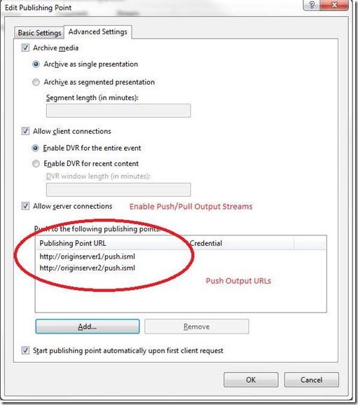
Push output stream means that the publishing point, upon being started or receiving new incoming streams, pushes the same long running fragmented MP4 streams to other publishing points using HTTP POST requests. Push output stream is often used to fan out encoder streams among the servers and provide redundancy in failover scenarios. To configure push output streams, you just need to set it up on the publishing point settings page like below:
Figure 7 – Configure Push Output Streams
One thing important to note here is that server pushes to those push output URLs simultaneously. In another words, they are NOT primary URL vs. backup URL. Instead, each one of them is an independent fan-out output path and carries the same data at the same time. If any one of the push output URL failed, the server will do automatic retry until it hits the retry limit (no limit with default configuration).
Pull Output Stream
Pull Output Stream is simply to enable downstream servers to pull from the current one (see section “Pull Input Stream”). It’s the same “Allow server connections” checkbox that enables both push and pull output stream option. Since the sever will be waiting for downstream requests for pulling, there is no other settings to be configured.
Client and Local Archive Output
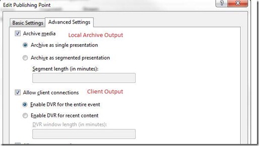
These two are the most important outputs to enable smooth streaming for the client. Client output means that this publishing point is allowed to serve smooth streaming clients that want to play this live content. Archive output allows the server to save the live streams to local files in smooth streaming format which can be later used for viewing as on-demand smooth streaming contents.
Figure 8 – Client Output and Archive Output
For archive output, you can have the option to save the entire event as a single presentation or create segmented presentations each of which has a fixed duration. This option is useful if you want to publish some early portion of the live event as on-demand contents before the event is finished. If you disable the archive option, server will use temporary files to store data that are needed for client’s DVR viewing and automatically delete them after the publishing point is stopped. So you still need to plan your disk space accordingly even if you disable archive option but still allow client DVR.
For client output, you can configure how much DVR window you want to make available to the client. For example, if it’s a 2 – 3 hour sports event and you have enough disk space for holding all the content, you can just use the default “Enable DVR for the entire event”. Or in another case, say you have a 24x7 always running live channel, you probably want to specify a DVR window limit so that the disk/memory usage is limited on both the server (potentially with archive disabled as well) and the client.
Putting it all together
Ok, so we’ve gone through all the possible inputs and outputs and their functionalities. Now let’s take a look at a IIS Live Smooth Streaming server solution as an example and see how these inputs and outputs work.
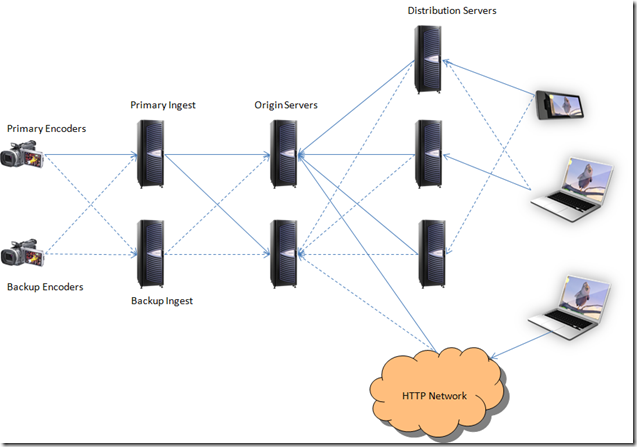
Figure 9 – Live Smooth Streaming Server Solution Example
This is a topology that quite some live event deployments were derived from. There are five layers in this diagram: encoder, ingest, origin, distribution and client. The solid lines are the normal data flow path while the dotted lines are the backup/failover paths. First, let’s go through each layer and see what their roles in this diagram are:
1. Encoders
Encoders take in live source feeds and encode them into smooth streaming formats. Then it uses HTTP POST to send the streams to Ingest servers which as configured with push input streams.
2. Ingest Servers
Ingest servers are mainly for taking in encoder streams and then fanning them out to origin servers. To effectively achieve stream fan-out and redundancy, ingest servers use PUSH output streams to push to multiple (two in this diagram) origin servers simultaneously. Because ingest servers typically don’t need to directly serve client requests or save local archives, these two options can be disabled.
3. Origin servers
In this solution, the origin server tier is the one that holds all the information about the live streaming, or a “single point of truth” as we would call. There are multiple origin servers running at the same time to provide scalability and redundancy. It has the capability to directly serve client requests. It can also be the source for distribution servers and synchronize past information with them if needed. To serve distribution servers, origin servers need to have the pull stream output enabled. To serve client requests either directly or indirectly through generic HTTP network which contains HTTP cache/proxy/edge servers, they need to have archive and client output options configured accordingly.
4. Distribution servers
Distribution servers can further scale out the network by offloading archiving and client request serving from the origin server tier. Distribution servers use pull input stream and are configured with multiple origin server URLs for redundancy. Distribution servers don’t have to be started at the beginning of the event because they know how to synchronize with origin servers to provide full DVR access to the entire live event. Please refer to the “Pull Input Stream” section above.
5. Clients
Client is not really a tier in the server network. But I’d like to point out that because of the stateless nature of the smooth streaming protocol, the retry/failover logic from the client can happen at the HTTP request level. In another words, for each fragment request, the client is free to use whichever server that’s available or provides the best throughput.
In terms of scalability, I think it is pretty obvious how it was achieved in this diagram. Now let’s focus on what are the different failover scenarios and how this solution can handle them.
1. Encoder failover
If any one of the primary encoders failed, the connection to the ingest server will be broken. As we discussed in “Push Input Stream” section, the server will keep everything running and expecting new encoder push streams to come in. Once the backup encoder is up and running pushing to the same publishing point using the same “streamID” values, the live stream can continue. From the client’s perspective, there will be a brief period of time that the latest live fragments for the broken streams/bitrates are not available. “Live” players that are on those bitrates will try to switch to other bitrates while players on other bitrates will not be affected.
Players in DVR mode will also not be affected since all servers are still capable of serving archived contents even when the live streams are down.
If the bandwidth between the encoders and the ingest servers are big enough, the backup encoders can behave as a hot backup meaning that they can encode and push to the same publishing points at the same time (see “Push Input Stream” section). Then in the encoder failover case, because there is a hot backup, the live stream can continue without any interruption.
2. Ingest failover
In normal condition, primary encoders push to primary ingest server which in turn pushes the same streams to two origin servers simultaneously. If, say, the primary ingest server failed, all connections among primary encoder, primary ingest server and origin servers will be broken. The encoder can detect this failure and starts pushing to the backup ingest server. The backup ingest server is configured exactly the same way as the primary ingest server and it will also in turn pushes the streams to the same origin servers, which will resume the live streams. The client side experience is similar to the encoder failover case.
Another option is to have the primary encoder pushing to both the primary ingest server and the backup ingest server at the same time if the bandwidth is not a concern. In that case, any single ingest server failover will not interrupt the live stream.
3. Origin failover
If one origin server failed, the other ones can serve as its backup immediately because they are all running and have the same data. Another aspect of it is that distribution servers also know where to re-request and retry the stream in the case of origin server failure. You can refer to “Pull Input Stream” section for more detail.
4. Distribution server failover
Just as origin servers, distribution servers are hot backups and can recover from server failure smoothly. This is especially true if the distribution server is used together with ARR (see “Pull Input Stream” section).
5. Client failover
Well, get another one. :)
Sometimes in real world deployment, you may have smart HTTP gateway devices that can automatically reroute HTTP requests to a server farm based on the server health information. In that case, you can just use URLs based on the virtual IP instead of hardcode multiple URLs. This would allow you to change a particular server tier without the need to modify settings in other tiers.
Summary
Hopefully by now you’ve got a better understanding about how input/out streams work in Live Smooth Streaming and how you can build a scalable and robust server solution with those options. Even though the example (as in Figure 9) we walked through is a compelling solution, it’s certainly not the only way to build your network. As the team who designed and built the Live Smooth Streaming platform, our goal is to make it powerful and flexible enough to build the best solution you need. Needless to say, there are definitely things that we missed or could further improve, especially considering this is the very first release of this new technology. So please do share your thoughts with us. We would love to hear your feedback and make our platform better for you. Happy smooth streaming!
